I decided to write up some notes on wiring a u-blox NEO-M8N GPS module to a Raspberry Pi 5 via GPIO. This was in order to configure it as a PPS (pulse-per-second) time source for ntpsec, giving a proper stratum 1 NTP server. On the Pis that I have on the rack, I also have a Uctronics NVMe and PoE hat. The PoE M.2 HAT occupies the HAT connector but the full 40-pin GPIO header is still accessible, albeit with 8 of the pins being ‘passed through’ the hat.
Why PPS matters
GPS alone (via NMEA sentences over serial) gives you time accurate to within ~100ms — good, but not stratum 1 quality. The PPS signal is a hardware pulse output from the GPS module once per second, locked to UTC. ntpsec can use this pulse directly via a GPIO pin, giving microsecond-level accuracy. Without PPS you’re stratum 1 in name only; with PPS you actually earn it.
USB GPS dongles typically don’t expose PPS — USB adds too much jitter. A module wired directly to GPIO is required.
Hardware
- u-blox NEO-M8N GPS module (HW-542 breakout board, V3.0) with SMA antenna connector
- Active GPS/GLONASS antenna with SMA male connector, magnetic base, 3m cable
- 5x female-to-female dupont jumper wires
- Raspberry Pi 5 (with PoE M.2 HAT — full GPIO header still accessible)
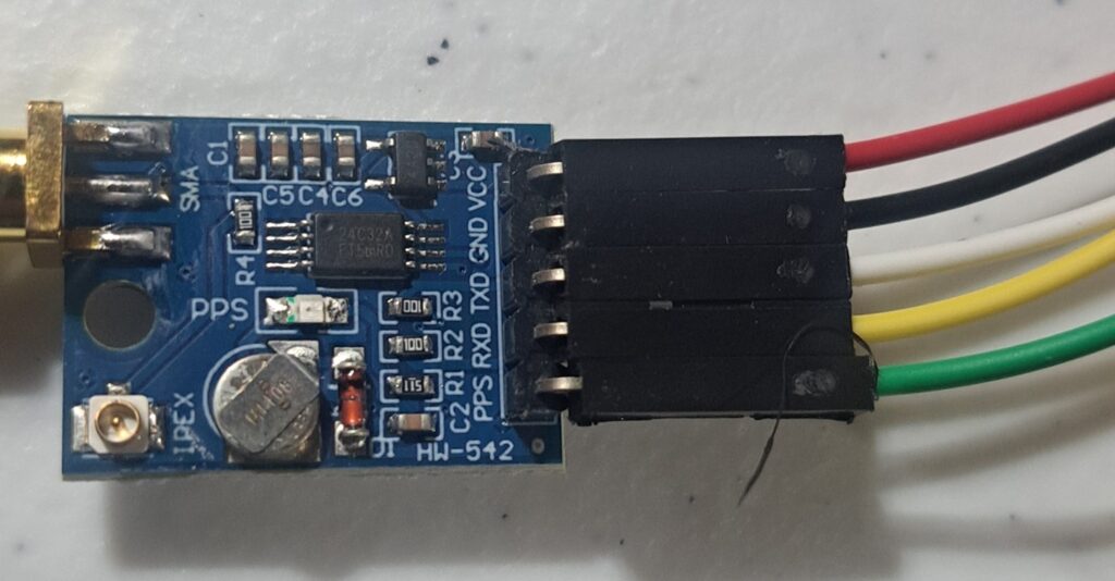
NEO-M8N pinout
The NEO-M8N has 5 pins. With the SMA connector on the left and pins on the right, reading top to bottom:
- VCC
- GND
- TXD
- RXD
- PPS
I assigned these as a specific colors like this:
Raspberry Pi 5 GPIO wiring
The Pi 5 GPIO header pinout (physical pin numbers, with USB/ethernet ports at the bottom of the board):
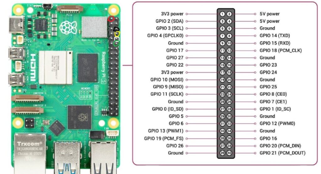
Wire colour assignments and connections:
| GPS Pin | Wire Colour | Pi Physical Pin | Pi Function |
|---|---|---|---|
| VCC | Red | Pin 1 | 3.3V power |
| GND | Black | Pin 6 | Ground |
| RXD | Yellow | Pin 8 | GPIO 14 (UART TX) |
| TXD | White | Pin 10 | GPIO 15 (UART RX) |
| PPS | Green | Pin 12 | GPIO 18 |
Important: TXD (white) on the GPS goes to RX on the Pi, and vice versa — they’re crossed, not straight-through. Use 3.3V only — pins 2 and 4 are 5V and will damage the module.
Pin 1 is at the top of the left (odd) row when the board is oriented with USB/ethernet ports at the bottom. There is a square pad on the PCB at pin 1 to help identify it. I’ve circled the pins in the colors that the wires go to for this.
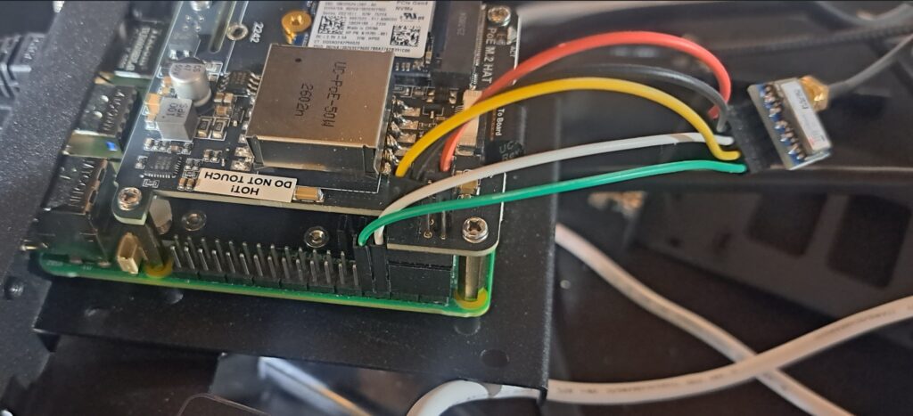
Once done, it should look like this (with the NVMe/POE hat on it, if you’re doing that):
Enable UART and PPS in config.txt
Add to /boot/firmware/config.txt:
enable_uart=1
dtoverlay=pps-gpio,gpiopin=18
The UART is not enabled by default on Pi 5. The pps-gpio overlay creates the /dev/pps0 device from GPIO 18.
Disable the serial console
This is a critical step. By default, the Pi uses the UART as a serial console. If the GPS module is connected and sending NMEA sentences before this is disabled, the NMEA data floods the console and triggers a kernel sysrq panic loop — the system becomes completely unresponsive.
Edit /boot/firmware/cmdline.txt and remove console=serial0,115200 from the line. It’s a single long line — just delete that part and leave everything else intact.
Also disable the serial getty service:
sudo systemctl disable serial-getty@ttyAMA0.serviceInstall and configure gpsd
sudo apt install gpsd gpsd-clients pps-toolsEdit /etc/default/gpsd:
START_DAEMON="true"
GPSD_OPTIONS="-n -s 9600"
DEVICES="/dev/ttyAMA0 /dev/pps0"
USBAUTO="true"
The -n flag tells gpsd to start polling immediately without waiting for a client to connect. Without it, ntpsec’s SHM shared memory never gets fed because nothing triggers gpsd to start. The device is /dev/ttyAMA0 — on Pi 5 the UART shows up as ttyAMA0, not ttyAMA10 or ttyUSB0.
Set correct permissions for pps0 — create a udev rule so it’s owned by gpsd:
sudo nano /etc/udev/rules.d/99-pps.rulesKERNEL=="pps0", OWNER="gpsd", GROUP="dialout", MODE="0660"sudo udevadm control --reload-rules
sudo udevadm triggerConfigure ntpsec
Edit /etc/ntpsec/ntp.conf. The SHM refclock lines are the key addition:
driftfile /var/lib/ntp/ntp.drift
statsdir /var/log/ntpstats/
statistics loopstats peerstats clockstats
filegen loopstats file loopstats type day enable
filegen peerstats file peerstats type day enable
filegen clockstats file clockstats type day enable
logfile /var/log/ntpd.log
logconfig =syncall +clockall +peerall +sysall
restrict default kod limited nomodify nopeer noquery
restrict 127.0.0.1
restrict ::1
server 127.127.28.0 minpoll 4
fudge 127.127.28.0 refid GPS
server 127.127.28.1 minpoll 4 prefer
fudge 127.127.28.1 refid PPS
pool 0.north-america.pool.ntp.org iburst
pool 1.north-america.pool.ntp.org iburst
pool 2.north-america.pool.ntp.org iburst
pool 3.north-america.pool.ntp.org iburst
127.127.28.0 is the SHM refclock fed by gpsd (GPS/NMEA). 127.127.28.1 is the PPS SHM refclock — set as prefer so ntpsec selects it once it’s stable.
Reboot and verify
Reboot after all config changes. Once up, check gpsd is seeing the GPS:
cgps -sWait for a 3D fix — this can take 5-15 minutes on a cold start, especially in a basement. Check PPS is getting pulses:
sudo ppstest /dev/pps0You should see one pulse per second. Then check ntpsec:
ntpq -pA healthy output looks like this:
     remote                refid      st t when poll reach   delay   offset   jitter
======================================================================================
-SHM(0)                  .GPS.        0 l    7   16  377   0.0000 -154.482   3.2339
*SHM(1)                  .PPS.        0 l    5   16  377   0.0000   -0.001   0.0008
*SHM(1) with .PPS. selected is what you’re after. The offset of -0.001ms is the kind of accuracy PPS gives you. SHM(0) GPS will show a large offset (~100-150ms) which is normal — the PPS is what matters.
Gotchas summary
- Serial console must be disabled before enabling the uart in config.txt — NMEA data will trigger a sysrq kernel panic loop if the console is active on the UART
- enable_uart=1 must be in config.txt — the UART is off by default on Pi 5
- GPSD_OPTIONS=”-n -s 9600″ is essential — without it gpsd waits for a client and ntpsec’s SHM never gets fed. 9600 is a baud rate that works.
- DEVICES must be set explicitly — gpsd installs with
DEVICES=""and does nothing useful until you fill it in - The device is /dev/ttyAMA0